
A duct leakage method statement names the standard and leakage class, the sections to be tested with their surface areas, the test pressures, the instruments and their calibration, the test sequence, the record sheet and who witnesses. On the day, each blanked-off section is connected to the test rig, raised to its test pressure, and the airflow needed to hold that pressure is read as the leakage and compared with the limit for its area and class.
What the method statement lists
The method statement is the document your commissioning agent approves before the first section is tested, and it should let anyone on site run the test the same way and reach the same verdict. A complete one covers these points:
- The standard and leakage class, usually DW/143 for the method with the limits from DW/144, and the class the specification sets for each system
- The sections to be tested, marked on the drawings, with the duct surface area of each in square metres
- The test pressure for each section, taken from the specification
- The test rig and instruments, with serial numbers and calibration certificates
- The sequence of the test, from connecting the rig to recording the result
- A blank copy of the record sheet that will be filled in for each section
- Who witnesses and signs each result
It should also say plainly which ductwork is in scope, because high pressure ductwork must be tested while low and medium pressure ductwork is tested only when the project specification asks for it.
Choosing and blanking off test sections
Test sections follow the way the ductwork is installed, such as a riser, one floor's branch or the run between two fire dampers, so each one can be tested as soon as it is finished instead of waiting for the whole system. Every section needs a known surface area, since the limit is a rate per square metre of duct surface and the allowable leakage for the section is that rate multiplied by its area. The area is worked out from the drawings, fittings included, and written on the marked-up drawing so the witness can check it.
Before the test, every opening in the section is blanked off with rigid plates or caps sealed at the edges, including grille and diffuser spigots, open branch ends and connections to equipment outside the test. Air lost through a poor blank counts against the section, so blanks are fitted with the same care as the duct joints, and one of them usually carries the spigot where the rig connects.
The sequence on test day
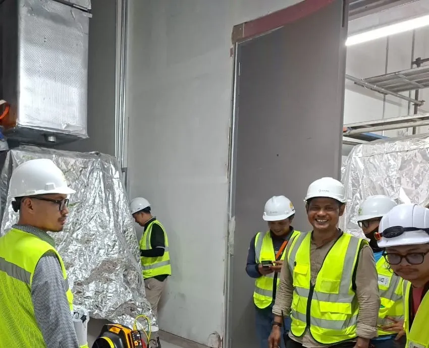
The tester and the witness first walk the section together to confirm it matches the drawing and that every blank is in place. The rig is then connected to the test spigot, with the pressure tapping placed in the section away from the connection so it reads the pressure in the duct and not at the rig outlet.
The fan is brought up gradually until the section reaches its test pressure and is held there until the readings are steady. The airflow the rig supplies to hold that pressure is the section's leakage, which the tester compares with the allowable figure and records on the sheet with a pass or fail before the witness signs. If a section fails, the leaks are traced along joints, seams and access doors, the contractor seals them, and the section is tested again, with both results kept on the record.
Working out the allowable leakage
DW/144 sets the limit in litres per second per square metre of duct surface as k × p0.65, where p is the test pressure in pascals and k depends on the class: 0.027 for Class A, 0.009 for Class B, 0.003 for Class C and 0.001 for Class D. Class A is low pressure ductwork, Class B medium pressure, and Classes C and D high pressure.
For a Class B section of 46 m² tested at 1,000 Pa, the limit is 0.80 L/s per m², so the section may leak up to 36.9 L/s. Showing this working on the record sheet lets the witness check the verdict on the spot. If a specification quotes SMACNA leakage classes instead, raise it before the method statement is approved, since SMACNA uses different units and its classes cannot be read across to DW/144.
Questions about the duct leakage test procedure
Is the test done under positive or negative pressure?
At the pressure the system runs under, so supply ductwork is normally tested under positive pressure and extract ductwork under negative pressure. The specification says which applies, and the method statement should show it for every section.
What instruments are used and what calibration is shown?
A test rig with a fan, a flow measuring device that reads the leakage and a manometer that reads the pressure in the section. The method statement lists each instrument with its serial number and calibration certificate, and those certificates must still be current on the test date.
What goes on the test record sheet?
The project, system and section reference with its drawing, the surface area, class and test pressure, the allowable and measured leakage, the result, the instrument serial numbers and the signatures of the tester and witnesses. A section that failed keeps its first result on the sheet next to the retest.
Is the test done before or after insulation?
Before, so a failed section can be found and sealed while the joints are still bare. If the programme forces a test on insulated ductwork the result is still valid, but the method statement should say so and allow time to strip insulation if a section fails.
Who needs to witness it?
Usually the commissioning agent, alongside the contractor's supervisor, and some specifications also ask for the consultant or the owner's representative. Invite them when the test date is set, because a result without the required signatures may not be accepted.
Book a duct leakage test
Send the drawings, the specification and your target dates, and we'll reply with a test plan and a quote.