
Testing, adjusting and balancing in data center construction
Testing, adjusting and balancing (TAB) is the work of measuring the air and water flow at every fan, pump, coil and terminal, then setting dampers, valves and fan or pump speeds until each flow matches the design. In a data center it covers the air from the CRAH and AHU units and the chilled water to their coils, it happens after installation and leakage testing and before functional tests, and it ends in a TAB report that lists every design and measured flow side by side.
What the three words mean in practice
Testing is measurement, where the tester reads the actual flow at each fan, pump, coil, grille and terminal with calibrated instruments and records it against the design flow schedule. Adjusting is the change made in response, such as partly closing a volume damper on a branch that takes too much air, opening a balancing valve on a coil that is short of water, or changing a fan or pump speed at its drive. Balancing is the loop of measuring and adjusting repeated across the whole system until every reading sits within the tolerance the specification sets, and it has to be a loop because closing one damper pushes air into every other branch on the same duct.
The order of the work matters as much as the steps. The tester first confirms the total flow at the fan or pump, then works through the branches and terminals, and only once the distribution is right is the fan or pump speed trimmed to the lowest setting that still delivers design flow everywhere, which keeps the system from wasting energy for the rest of its life.
What gets balanced in a data hall
Cooling in a data hall reaches the racks either through a raised floor and perforated tiles, through ducts and grilles, or straight into a contained aisle, and in every case the air comes from CRAH or AHU units whose coils are fed with chilled water. TAB therefore covers both sides of the same cooling path, together with the smaller systems that keep the support spaces running:
- Supply airflow and fan speed setting of each CRAH and AHU unit
- Airflow through the floor tiles, grilles or diffusers along each row, where the design gives a flow for them
- Return, fresh air and pressurisation flows
- Ventilation and extract in electrical rooms, battery rooms and plant rooms
- Chilled water flow at the pumps, the main branches and each cooling coil
Why balance matters once IT load arrives
An unbalanced system still runs, and in an empty hall it can feel cold everywhere because there is almost no heat to remove. The problem shows up once IT load arrives, when a coil short of chilled water cannot deliver its rated cooling and a row short of air lets the servers draw warm exhaust air back into their inlets, and both appear as hot spots that operators then chase by lowering setpoints or running more units than the design intended.
Correcting the flows during construction, with ceilings open and the hall empty, is far simpler than correcting them in a live data hall where every damper or valve change needs a permit and a maintenance window. Balanced flows also make the later heat load and functional tests meaningful, since a unit that fails a test on a balanced system points to a fault in that unit rather than in the distribution around it.
Where TAB sits in the programme
TAB needs a finished, clean system that runs in its normal mode, which means ductwork installed and leakage tested, pipework flushed, fans, pumps and controls started, final filters fitted and every damper and valve still within reach. It therefore comes after installation and leakage testing and before functional tests, and the controls engineer usually tunes setpoints such as the pump differential pressure from the TAB results once balancing is done.
Starting too early is the most common mistake, because flows set before the ceilings close, before the controls are stable or while temporary filters are still in place will move, and that part of the work has to be repeated. A TAB plan agreed at the start, listing the systems, the procedure, the tolerances and the order of work, lets the site team know what has to be ready before each visit.
What the owner receives
The owner receives a TAB report that records every design and measured flow side by side, with the final damper and valve settings, the instruments used and the signatures of the tester and the witness. The commissioning agent reviews it before functional tests begin, and the facility team keeps it as the baseline for every later change, such as adding a row of racks or replacing a CRAH unit, when they need to know what each unit and coil was delivering at handover. For that reason the report should show readings as measured, including any terminal that could not reach design flow and the reason why, rather than figures rounded to match the design.
Questions about TAB in data centers
What exactly gets adjusted?
Volume dampers in ducts and at grilles, balancing valves on chilled water branches and coils, and the speed of fans and pumps at their drives. Once each one is set, its position is marked or locked so later trades do not disturb it.
At which commissioning level does TAB happen?
TAB is usually completed within Level 3, alongside pre-functional checks and start-up, so that the Level 4 functional performance tests run on a system that already delivers its design flows. Some projects number the levels differently, so the commissioning plan says exactly where TAB sits.
Which standard does TAB follow?
Usually the NEBB procedural standards, or another TAB procedure that the project specification names, and the procedure and tolerances should be agreed before work starts. Pariksa works to the NEBB procedural standards unless the specification calls for a different procedure.
What instruments are used?
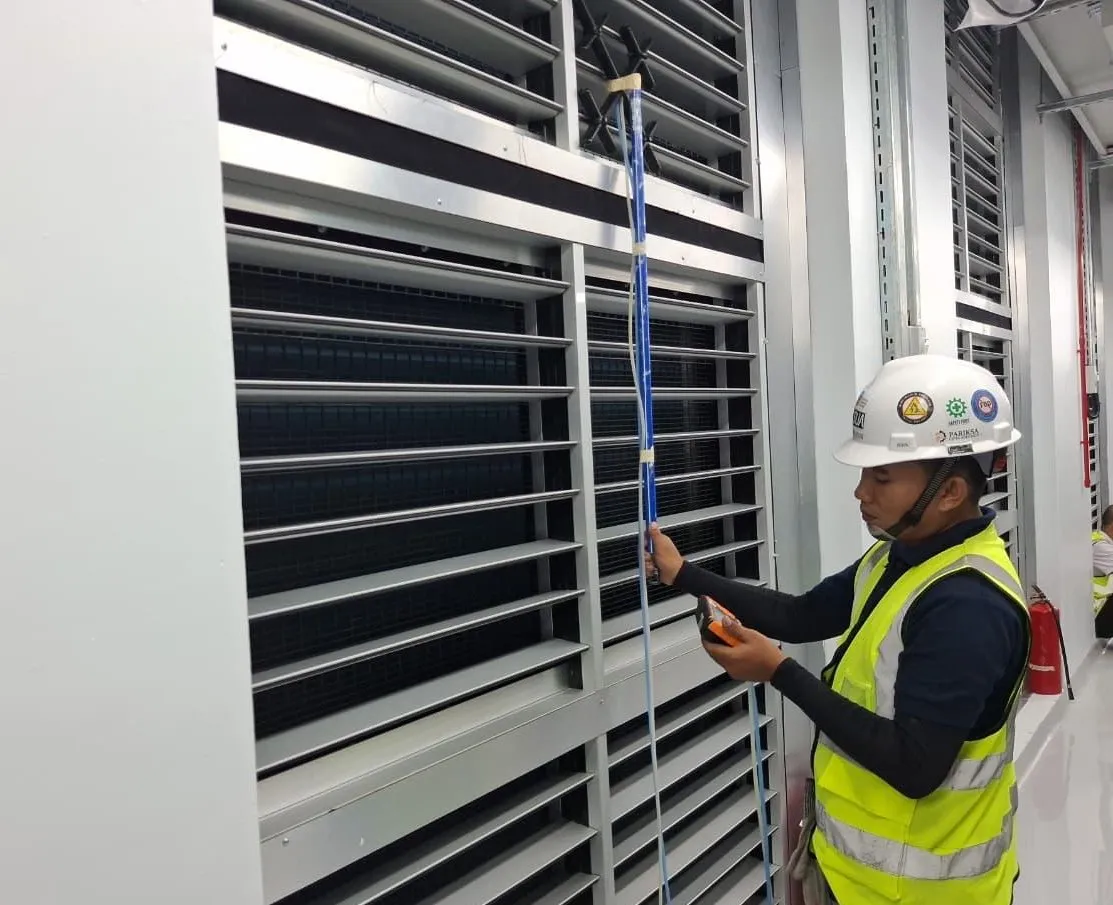
Flow hoods for grilles and diffusers, anemometers for readings across louvers, coils and duct traverses, manometers for static and differential pressure, and ultrasonic or differential pressure flow measurement for chilled water. Each instrument needs a current calibration certificate, and its serial number goes in the report.
How close to design do the flows need to be?
NEBB's general rule is that measured flows end within ±10% of design, but many data center specifications set tighter or asymmetric tolerances, for example allowing more flow above design than below it, so the specification governs.
Book testing and balancing
Send the drawings, the flow schedule and your target dates, and we'll reply with a test plan and a quote.